Incineration is a technology based on the thermal treatment of waste by combustion of the organic fractions as present in waste, under combustion conditions with an excess amount of oxygen relative to the amount of fuel supplied via the waste.
A wide range of combustion technologies have been developed over the centuries, such as fluidized bed incineration, moving grate (or stoker) incineration, pyrolysis, gasification (controlled air) and many other technologies.
Within this wide spectrum ROTARY KILN INCINERATORS can be considered to be the absolute workhorse of all options, being the most versatile in the acceptance of wastes.
ROTARY KILN INCINERATORS are typically applied in the following KEY MARKETS:
- Medical and infectious waste incineration,
- Thermal desorption (soil cleaning),
- Hazardous waste incineration, including:
- Solid wastes,
- Sludge, slurries,
- Combustible liquids,
- Waste waters,
- High chlorinated hydrocarbons and PCB’s,
- Petrochemical wastes,
- Refinery wastes,
- Pharmaceutical wastes.
BEST AVAILABLE TECHNOLOGY (BAT):
for medical waste:
- Guaranteed complete destruction of biological tissues, infectious substances (in contradiction to processes operating at lower temperatures such as micro-wave or steam sterilization based processes). No visible remainders are present in the produced ashes, simplifying final disposal.
for hazardous chemical waste:
- The fundamental advantage of a rotary kiln compared with other technologies (such as fluidized bed, moving grate) is that material supplied to the system will come out of the system, regardless size and properties. Also liquids, sludge, metal drums can be simultaneously treated on a continuous basis, without causing disruption or unscheduled shut downs. This at well controlled combustion conditions in compliance with all environmental regulations, also enabling efficient energy recovery.
ROTARY KILN INCINERATORS – TECHNOLOGY AND OPTIONS
Any incineration process as supplied by Dutch Incinerators as turn-key project is adapted to the specific needs of every client. Several options are available for each step in the process. Generally speaking, the overall waste treatment process can be represented with the following block diagram.
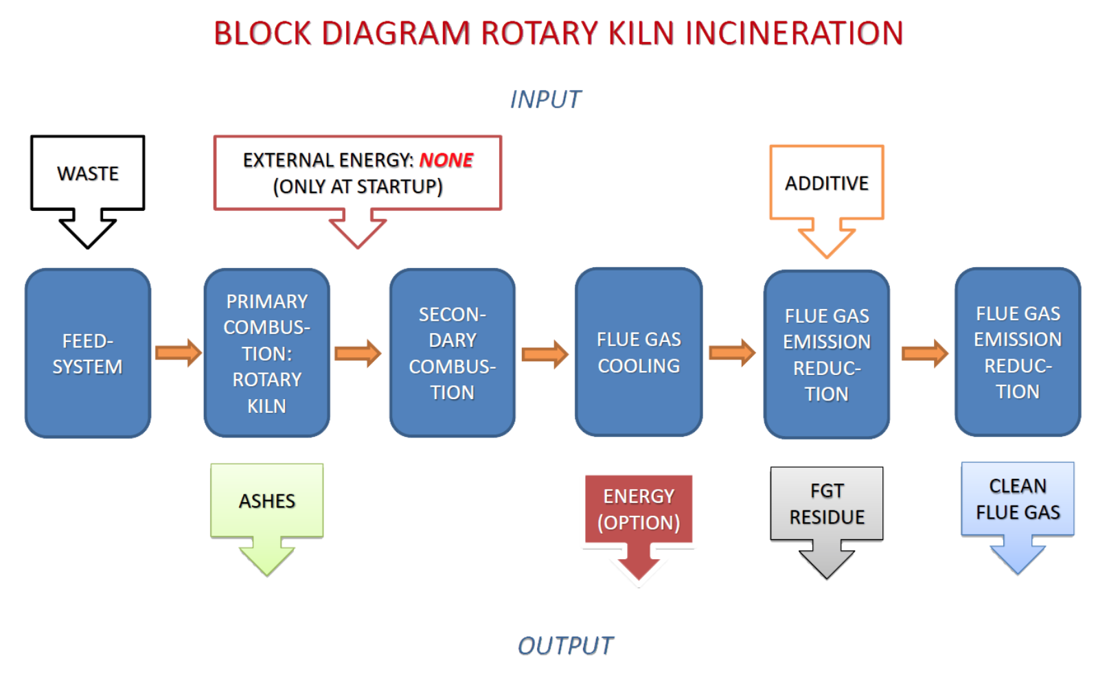
FEED SYSTEM:
The ROTARY KILN INCINERATOR as provided by Dutch Incinerators is capable of accepting and treating a wide range of wastes.
Options and features:
- The feed system is typically completely enclosed; uncontrolled emissions of hazardous, infectious substances or smoke from the waste feeding system are eliminated.
- Solids are usually supplied via a sluice mechanism and a hydraulically operated ram feeder.
- A bin tipper or waste grabber can be used to supply the waste to the sluice, depending upon on the waste is supplied to the treatment facility.
- Alternatively, solids and sludge can be pumped by solid waste pumps and directly transferred to the combustion process independently from other waste supply options.
- Bulk solids can be supplied with (shaft-less) screw conveyors as well, if the waste is available in bulk form.
- Containers, drums can be supplied as a whole directly to the feeding system, if emptying or shredding is not practically appropriate.
- Alternatively, solids or solid containing drums, IBC’s etc. can be shredded prior to feeding. This not only for size reduction for the furnace and feed system but also to reduce peak loads in the supply of combustibles to the combustion process, thus stabilizing the combustion process.
- Mechanical components are typically installed in such a way that maintenance is easy and risk-free. Direct contact between waste and vulnerable components such as hydraulics or instrumentation is minimized.
- Special attention is always given to safety: reduction of emissions and the prevention of fire and explosions in the feed system, a common problem in the waste incineration technology is top priority in the design and construction.


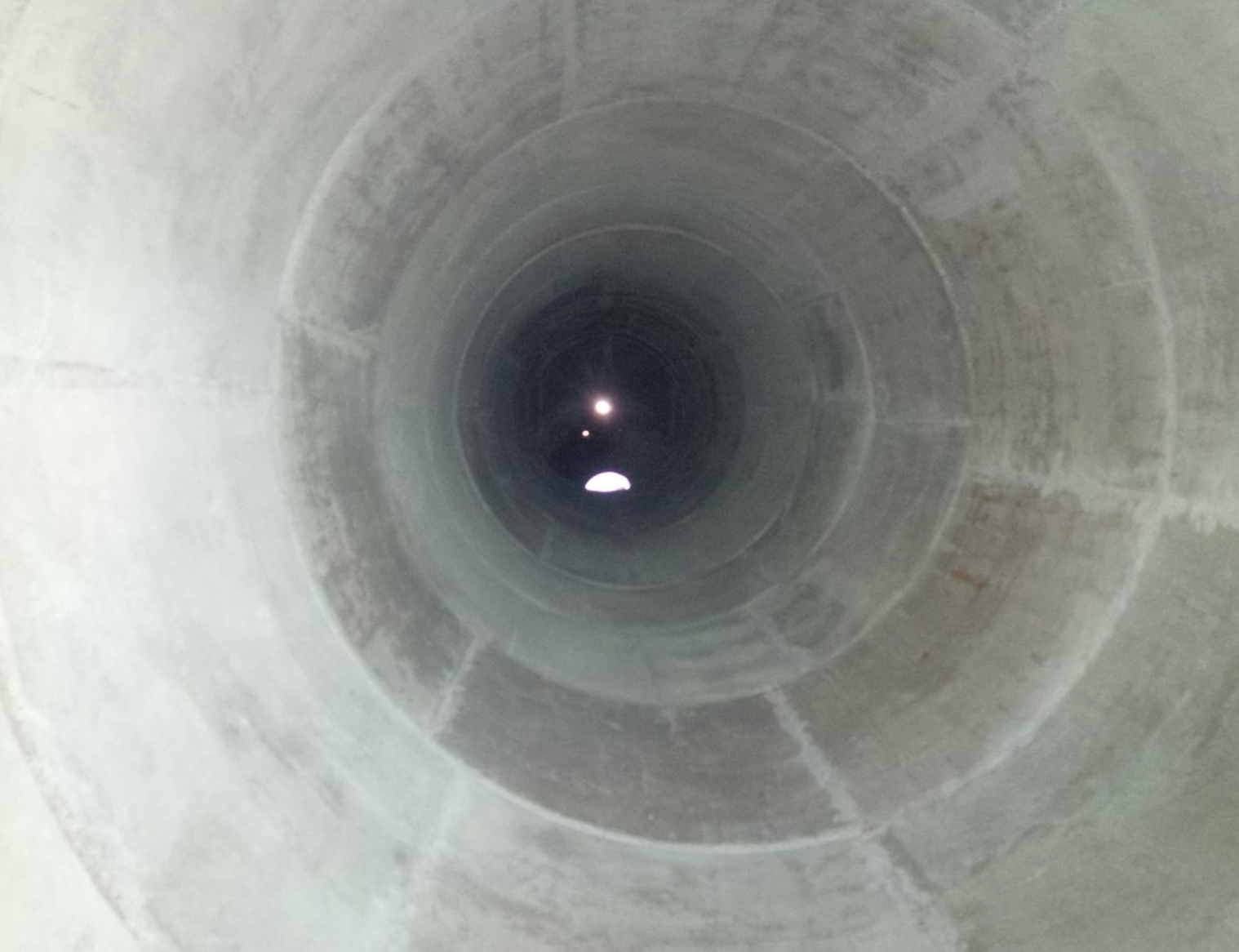
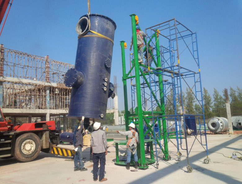
Rotary kiln
The rotary kiln is the heart of the ROTARY KILN INCINERATOR, being the zone of primary combustion.
Options and features:
- The rotary kiln can be constructed to the co-current or counter-current concept. In the co-current concept, the waste and combustion air move in parallel over the axis of the kiln. Flue gas discharge from the kiln is at the same end of the kiln as ash discharge. In the counter-current concept, the waste and combustion air move in the opposite direction over the axis of the kiln. Flue gas discharge is located at the feeding point of the waste, ambient combustion air supply is located at the ash discharge side of the kiln.
- Dutch Incinerators has experience in the construction and operation of both types of rotary kiln concepts.
- Each concept, co-current or counter-current rotary kilns, have their specific benefits and drawbacks.
- The major advantage of counter-current kilns being the fact that the ash temperature as discharged by the kiln is lower. This creates less issues with slagging and is therefore more reliable and less complex in day to day operations. No need for a water bath for (molten) slag cooling and discharge, no risk of clogging near the kiln outlet, less mechanical issues and maintenance on the kiln outlet section. Metal recovery from the ashes is also possible as the ashes are produced in a counter-current kiln as fine grains and dust.
- The major advantage of co-current kilns being the fact that the thermal load to the kiln feeding system is lower as flue gas temperature at the feeding side of the kiln is lower.
- From a thermal point of view, co-current kilns are more suitable for the treatment of higher calorific wastes, as waste combustion is more gradual due to the temperature gradient over the kiln. Counter-current kilns are more suitable for the combustion of low or variable calorific wastes, as the hot flue gas helps to initiate ignition of the waste at the feeding point of the kiln and helps to evaporate water as supplied via the waste.
- Based on long term experience, considering all the above from a practical point of view, it can be concluded that counter-current kilns are more reliable and more simple in day to day operations, under the condition that the feed system is properly designed, the latter being the case for the specific Dutch Incinerator designs.

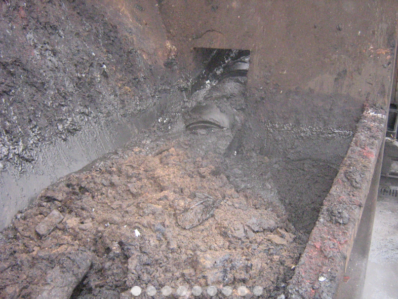
Ash discharge
The ash discharge of the ROTARY KILN INCINERATOR based on the counter-current rotary kiln concept accepts and discharges the remaining ashes as produced by the primary combustion zone.
Options and features:
- Typical TOC (Total Organic Carbon) in the bottom ash residue less than 3 mass percent.
- Manual ash discharge, using containers (lowest cost option).
- Continuous automatic discharge using screw conveyors in combination with automatic size separation of bigger items not suitable for screw conveyor discharge, such as drums, slags and other larger items. Larger items removed manually from the system.
- Fully automated discharge of both ashes and larger items.
- Recycling of metals by automated metal separation from the produced ashes.
Post combustion
The Post Combustion zone of the ROTARY KILN INCINERATOR ensures complete combustion of hazardous compounds in the flue gas, in line with international environmental regulations for the combustion of hazardous wastes.
Options and features:
- Combustion characteristics are in compliance with EU regulations (EC Directive 2000/76/EC and subsequent revisions): minimum 850 or 1100 °C at minimum 2 seconds residence time, the higher temperature needed for wastes with a higher organic chlorine concentration.
- Automatic start-up of the Post Combustion back up burner in case of an uncontrolled drop of the flue gas temperature below the above minimum temperature values.
- Non-clogging construction concept, a specific feature of the Dutch Incinerators design, based on hands-on experience. A common problem in waste incineration is the gradual build-up of dust and slags in the post combustion zone; Dutch Incinerators successfully resolves these issues with specific design measures. Visit our reference sites to see how this common issue is practically resolved!
Flue gas cooling – energy recovery
The ROTARY KILN INCINERATOR process produces hot flue gasses, suitable for energy recovery, depending upon client requirements.
Options and features:
- Smaller systems typically use water injection to reduce flue gas temperature, prior to final flue gas emission reduction. The most cost effective solution, although without energy recovery.
- Alternatively the flue gas can be mixed with ambient air to reduce flue gas temperature, a simple and reliable method for incinerators with a small thermal input.
- Energy recovery is a viable option for incinerators with a higher thermal input, starting from 3 MW, depending upon the balance between investment costs versus returns. A wide range of options is available:
Energy recovery by the production of hot ambient air
Hot air can be used for:
- Production of chilled water via an absorption cooling machine, typical application: medical waste storage room cooling.
- Combustion air preheating to support other combustion processes.
- Drying processes using hot air.
- Steam generation or hot water production.
Energy recovery by the production of steam
Steam can be used for:
- General energy supply as utility steam for other production processes.
- Electricity generation using a steam turbine (up to approx. 1.5 MW electrical output for the product range of Dutch Incinerators).
Energy recovery based on thermal oil
Thermal oil can be used for:
- Direct high temperature heating of other production processes.
- Steam or hot water generation in case of an excess of energy.
- Chilled water production.
Energy recovery based on the Organic Rankine Cycle (ORC)
ORC enables energy recovery and electrical power generation there where steam based energy recovery is not practically feasible, specifically for energy recovery at lower flue gas temperatures and smaller thermal input capacities.


Flue gas emission reduction
The Flue gas emission reduction process of the ROTARY KILN INCINERATOR reduces the concentration of contaminants as present in the flue gasses to levels below the applicable emission standards. Typically, Dutch Incinerators designs comply with EU regulations in this regard, the most strict on the planet. Several systems and options are available to meet the applicable emission standards.
Options and features:
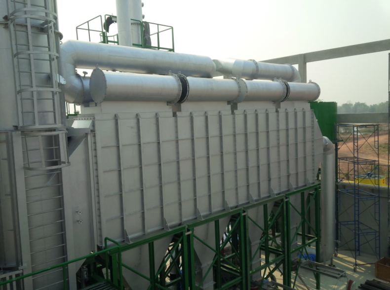
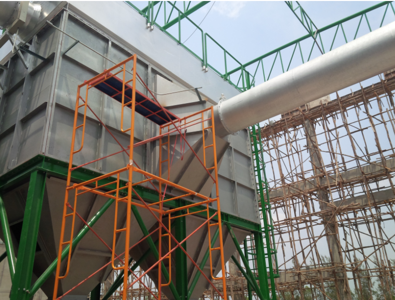
Dry scrubbing emission control systems
These scrubbing systems are characterized by the fact that the flue gas is treated without complete saturation of the flue gas stream with water (with other words, without completely quenching the flue gas stream with water). Typically they include a dosing mechanism for additive(s), reaction and residence chamber and a bag filter for final dust removal. The choice of additive depends upon the types of contaminants to be removed and financial considerations, mainly operating costs. Dutch Incinerators can provide the following technologies:
- Dry scrubbing based on dry lime injection (Calcium based).
- Semi dry scrubbing based on lime slurry injection with complete evaporation (Calcium based).
- Dry scrubbing based on sodium bicarbonate. Higher emission reduction efficiencies can be achieved with this relative new technology also resulting in lower operating costs overall. Generally the preferred option comparing with conventional lime based technologies.
- Activated carbon addition to capture dioxins, heavy metals.
Dry scrubbing systems have the following advantages and disadvantages compared with wet scrubbing:
Advantages:
- The flue gas leaves the system at temperatures above the dew point of water and most common acidic components in the flue gas.
- This reduces or eliminates the visible water vapor plume on the stack.
- This reduces or eliminates corrosion issues, quite common with improper designed or operated wet scrubber systems.
- The implementation of a bag filter results in the lowest emission of dust (PM, particulate matter or TSP, total suspended particles), typically lower than 5 mg/m3, corrected.
- Aerosols, such as “white smoke” are effectively captured in a bag filter.
- No make-up water required.
- No waste water treatment required.
- Is capable to achieve emission levels within EU regulations as a single step solution, depending upon the type of additive used, design of the system, acidic gas loads and dosing capacities.
Disadvantages:
- Generally higher initial investment costs, due to the bag filter, optional sodium bicarbonate grinder, lime make up systems, additive storage systems and reaction and residence time ducting.
Wet scrubbing emission control systems
Wet scrubbing systems are based on the reaction of acidic flue gas contaminants with caustic (NaOH), present in a diluted form in the wet scrubber circulation fluid.
Wet scrubbing systems have the following advantages and disadvantages compared with dry scrubbing:
Advantages:
- Capable to achieve very low emission concentrations on acidic flue gas compounds with relative simple technology.
- Capable to achieve reasonably low dust emission concentrations, typically below 50 mg/m3 corrected (but apart from specific cases not low enough to meet EU regulations if applied as a single step solution).
- Relative low investment costs.
- Relative simple to operate and control.
- Capable to absorb wide and fast fluctuations in acidic flue gas component supply, as the scrubber water and sodium based chemistry acts as a fast acting buffer to absorb these contaminants.
Disadvantages:
- A wet scrubber consumes water. This needs to be available in sufficient quantities.
- A wet scrubber produces waste water. This needs to be treated. Smaller quantities can be treated in the incineration process itself, but generally speaking some means of water treatment is required.
- Corrosion might me a problem, although more an operational problem for a properly designed system (not maintaining pH within certain margins).
- Wet scrubbers have more problems to reduce aerosols emissions, such as “white smoke” as produced by a hazardous waste incinerator depending upon waste input. Specific measures are available to reduce this problem, but efficiency is lower than a dry scrubbing based system.
Combination of dry- and wet scrubbing systems.
A combination of a dry- and wet scrubbing system might be the optimum choice in specific cases, considering the above, resulting in the most optimum emission reduction solution for the total facility as the advantages and disadvantages of each option can be balanced and optimized.

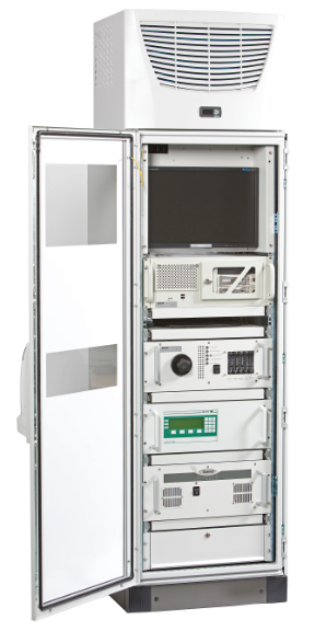
Flue gas emission monitoring
Flue gas emission monitoring for the flue gasses leaving the flue gas emission reduction system of the ROTARY KILN INCINERATOR is required to ensure that final emissions comply with the applicable regulations. Emissions are typically monitored on a continuous basis (CEMS, continuous emission control system); results are represented in the central control room, stored in a data bases for reporting to authorities or can directly be transferred to the authorities or external parties via a direct datalink. All CEMS systems as provided by Dutch Incinerators are produced by top quality suppliers, constructed and tested to international standards and approvals.
Options and features:
- Typical CEMS analysis parameters: SO2, HCl, NOx, HF, CO, O2, H2O, CO2, TOC, PM (dust), opacity and more compounds, all upon request and client requirements.
- Extractive CEMS systems, typically used after a wet scrubbing system.
- In-situ CEMS systems, typically used after a dry scrubbing system (lower in investment than an extractive system).
- Particulate Matter CEMS, specifically applicable for wet scrubbing systems, where optical dust measurements give a misreading.
- Optical PM CEMS and opacity measurements as commonly used on dry scrubbing systems.


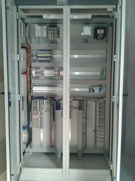
Plant automation
The ROTARY KILN INCINERATOR is delivered as turn-key process and is completely automated using the latest technologies.
Options and features:
- The complete process is automated using a PLC, using top quality European automation components.
- Monitoring of the process is typically done using 2 interfaces (HMI, human-machine-interface), one unit near the processing system for direct operator control, one available in a central control room for supervisor monitoring.
- Remote access via internet from anywhere on the planet can be integrated, upon client request.
- The plant automation system typically includes continuous data acquisition and storage, reporting, trending, IO visualization and overview of electrical systems and can be adapted to specific client requests.
- Plant automation visualization screens can be tailor-made, depending upon client requirements.
- Additional visualization screens can be added, implemented, for instance for public information or sales of actual emissions or operating conditions.


Want to know more? Download product leaflet here or send us an email.