
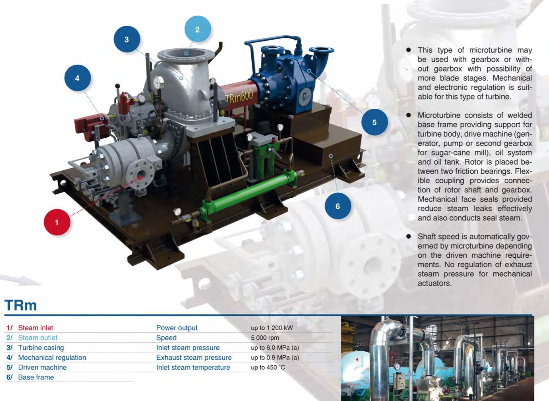
Steam Turbine
• Micro turbines up to the capacity of 3 MW
• Steam turbines up to the capacity of 10 MW
• Turbines with overhung impeller
• Turbines with the impeller between the bearings
• Turbines with a frequency converter
• Multi-stage turbines
• Gas expansion turbines
• Cogeneration units
Product Types

By-pass stations
• By-pass stations for steam turbines up to the capacity of 660 MW
• Reducing stations towards steam parameters decrease
• Offtake piping
• Pressure piping
• Steam line

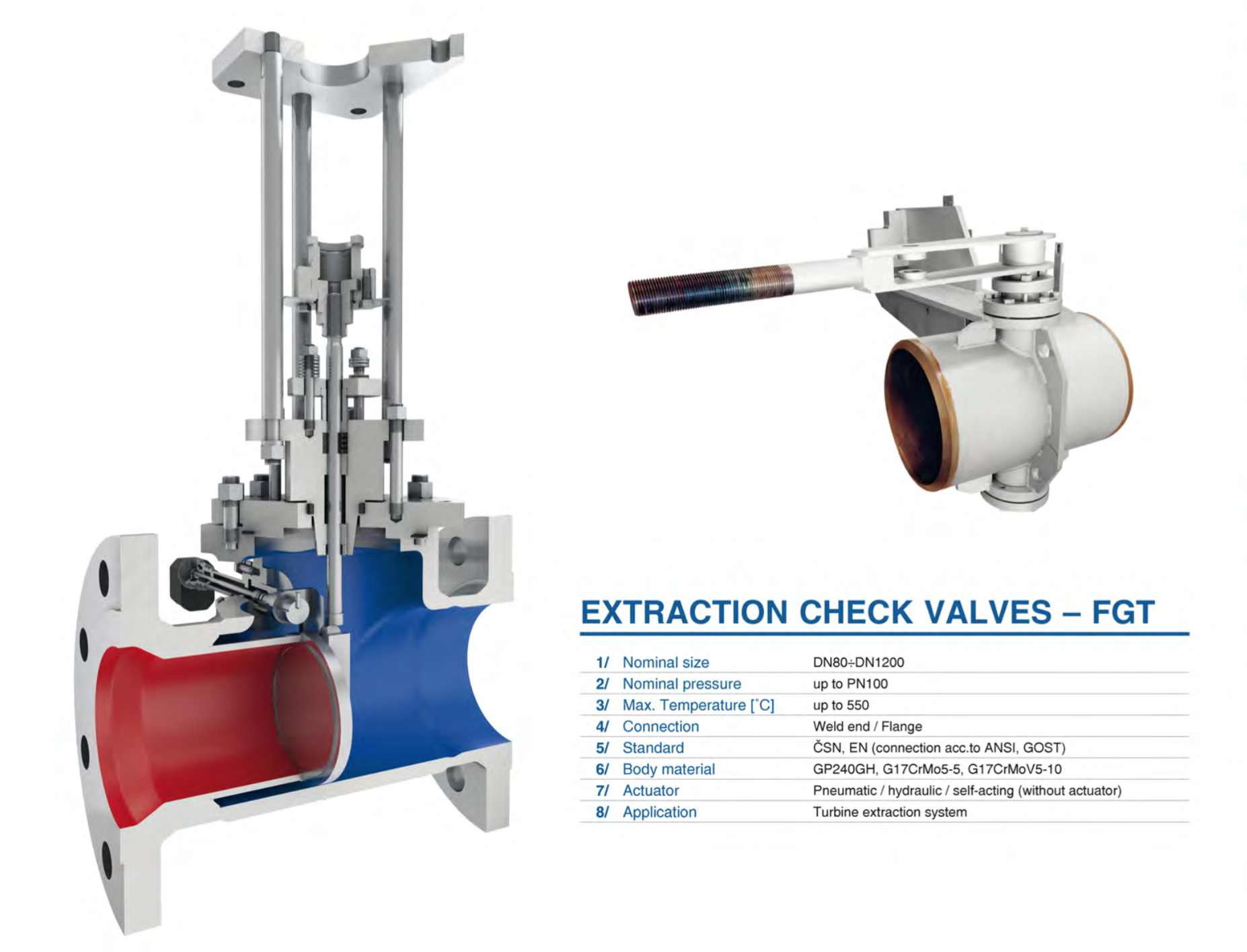
Valves and flaps
• Control and stop valves
• Pressure reducing valves
• Emergency stop valves
• Blow-down and continuously blow-down valves
• Safety valves
• Back check-valves, flap valves
• Control and stop flaps
• Ball valves
• Sieves
Product Types


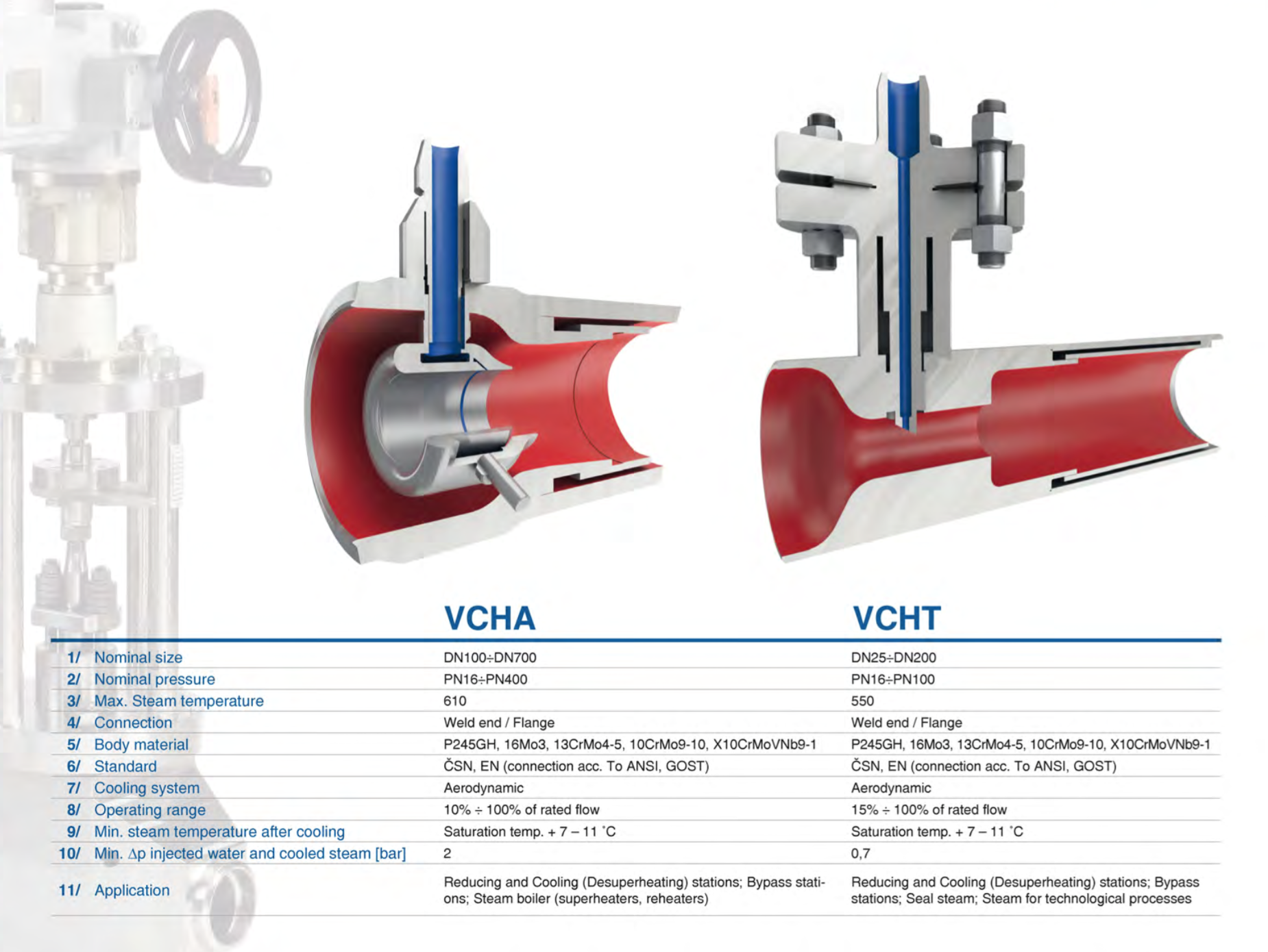
Desuperheaters
• Desuperheaters for by-pass stations
• Desuperheaters for reducing stations
• Desuperheaters for small dimension steam piping
• Desuperheaters for steam lines
with high mass flow rates
Product Types

Oil systems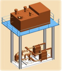
• Integrated oil systems for steam turbines up to the capacity of 1000 MW
Steam traps
- Float steam traps
- Thermostatic steam traps with bimetallic regulator
- Thermostatic steam traps with membrane regulator
Electro-hydraulic
Electro-hydraulic control system based on microprocessor-electronic controller with high-pressure hydraulic system.
Advantages:
- Simple design – safety (reliability) Accurate and quick regulation
- Automatic turbine start-up to operation speedaccording to chosen starting curve
- Possible remote control of the operating regulation
- Possible data aquisition with data bus
- Valve modification according to (DN, PN)
- Independent oil system – less troubles withImpurities and oil filter cloggingControl valve (RURV) of single-stage turbine in connection with high-pressure electro-hydraulic system has very important advantage in simplicity compared to low-pressure control system (used with steam turbine). Mechanical gear- boxes (levers) and complicated oil servo-actuator are replaced with simple fabricated hydraulic cylinder. The photograph shows mechanical simplicity of high-pressure system with given accuracy and reliability. Control valve (RURV) doesn ́t have clutches or joints thanks to these don ́t exist mounting clearances which influence accuracy and service life.
Design Engineering
Pipeline systems in power generation and industry
- Technical feasibility study, ideal balance design of energy equipment and units
- Comprehensive project documentation for planning permission (basic design), building design (detail design) and actual design of technological equipment and operation sets for power plants, heating plants and industrial estates in compliance with valid law and technical regulations.
- Project documentation of repairs and reconstructions of selected technological equipment and operation sets of nuclear power plants classified as BT2 and BT3 acc. to Notice 132/2008 in conformity with requirements of Notice 309/2005
- 3D design and space visualization of technological equipment and pipeline systems including safety valves exhausts, steam trap, draining and air-vent in 3D CAD Edge and Smap3D Plant Design
- Calculation, piping and instrumentation diagram/drawing showing pipeline components, valves, energy equipment and instrumentation MaR including position of pipeline and auxiliary steel constructions
- Design and calculation verification of unnormalized pipeline components through SW ANSYS PROFESSIONAL
- Piping Flexibility Analysis through SW CEASAR II
- Design of pressure and pressure-free vessels, reducing, desuperheating (cooling) and bypass stations including safety pressure equipment in compliance with valid law
- Project documentation of pressure tests and cleaning processes after installation
- Control algorithm design for regulation, warming-through and commissioning of technological equipment, creation of operating regulations
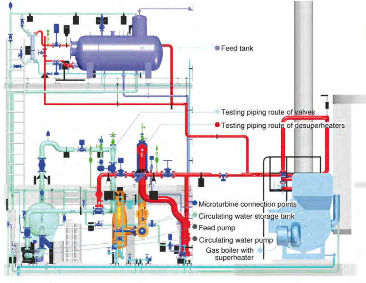
Experimental and Development department
Control valves testing
- testing pipe route designed according to CSN EN 60534-2-3 provides flow characteristics and normal flow coefficients kvs of control valves – DN15 – DN150, u tp kv = 100m3/h
Desuperheaters testing
- testing route designed for nozzle optimization of mixing cooler of superheated steam
- practical verification of newly designed desuperheaters with possibility of size measuring of atomized drops
- testing parameters of reduced inlet steam – temperature up to 240°C, pressure approx.. 12 bar(g), amount up to 4 (¸6) t/h
- testing parameters of inlet cooling water – temperature up to 15¸100°C, pressure up to 20 bar(g), amount up to 2.0 t/h
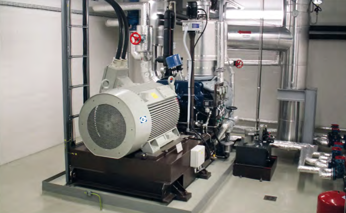
Microturbine testing
- Testing route designed for verification of TR service availability before dispatch to customer (check of operating vibrations and oil temperature in bearings)
- Testing parameters of inlet steam – temperature 240°C, pressure 12 bar(g), flow 4 (¸6) t/h

Installation
Steam turbine installation
- Condensing steam turbines
- Backpressure steam turbines
- Microturbines
- Gearbox installation
- Heavy manipulation into and in installation area
Turbine Current and overhaul repair
- Spare parts supply
Generator installation
- Air-cooled generators
- Hydrogen-cooled generators
Pipeline system installation
- Pipeline installation from P91, noncorrosive and cabon material
- Pipeline oil systems
- Water-steam pipeline
- High-pressure hydraulic pipeline
- Industrial gas system
- Installation and adjustment of control valves
- Installation and adjustments of servo-actuators
Additional installations
- Installation of hydrogen system
- Installation of oil system
- Installation of integrated oil system
- Installation of pumps and feed pumps
- Installation of coolers (desuperheatres)
- Installation of heaters, tanks and pressure vessels
- Installation of steam turbine condensers
- Measurement of energy quantities
- Vibration and movement of rotary machines
- Diagnostics of steam traps operation

REFERENCES: Equipment and Methods of Solution of Power-Plant Units
Want to know more? Download product leaflet here or send us an email.