Mineral wool production lines with the capacity of up to 12 tons of the final product per hour. Currently the company can offer the delivery of full stone wool production line or replacement of its parts. Final product line width can be designed in standard sizes of 1200, 2000, 2400 mm or based on customer’s request. All the machines and systems are designed with high regard for the emissions with respect to the BAT for mineral wool lines, industrial emissions directive 2010/75/EU, TA-FUFT 2002.
Company is also a leader in the field of exhaust gas cleaning systems for a wide variety of industrial operations. Within the rock wool production lines company provides cleaning systems for waste gases from the cupola furnace and curing oven. Outlet emissions from our cleaning systems are well below limits set by ”Industrial emissions directive 2010/75/EU”.
Cupola Furnace
Manipulation with material, weighing
Raw material such as basalt, dolomite and coke is transferred by trucks or railway and stored in piles in an open-air warehouse. The transport from the piles to the receiving container is executed by loaders. The material is poured from the receiving container to the primary conveyor by the means of a vibrator. The primary conveyor transports the raw material into daily containers that are intended for 4 different elements (basalt, cinder, dolomite, coke) with the use of a distribution conveyor located in the upper part of the containers. There are four weighing (feeding) systems under the containers that automatically fill up the cupola furnacewith the exact required volume of raw material. The weighed material is transferred to a conveyor and transported to a feeding conveyor that takes the material directly to the cupola furnace.
Cupola furnace
For many years company has been successfully using coke cupola for melting of raw materials. From the cupola flue gas system hot air with temperature up to 650 °C is blasted to cupola and reach the melt capacity of up to 16 tons per hour.
The material (stone with additives) is fused in the cupola furnace with the use of coke. The cupola furnace consists of a feeding, extracting and fusing zone. The upper part of the cupola furnace consists of a receiving hopper fitted with a rotary feeding neck and gate with air-operated closing cone and feeding tube that distributes the material evenly. The minimal level of material in the feeding tube is monitored by a surface sensor. Combustion products are conducted away from the extracting zone.
The fusing zone consists of a conical, water-cooled casing. The bottom part widens for easier dumping of the cupola furnace. There is a distributing air duct in the upper part of the fusing zone from which the preheated air is blown through blowers to the fusing zone. The molten mass flows from the cupola furnace through a siphon and distribution channels to a spinning machine. When the fiberizing process is interrupted, the molten mass is diverted through an emergency drain down below the cupola furnace.
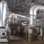
Cupola Flue Gas System
The exhaust gas created during the operation in the cupola furnace are conducted into the cupola flue gas system. In case of emergency or when the temperature of flue gas exceeds 360°C, the exhaust gas is conducted into the atmosphere through an emergency chimney with the use of an ejector with a ventilator. The flue gas is conducted by piping into a cooler located in front of the filter. The heat exchanger cools down the flue gas (by fresh air) or heats it up (by clean flue gas) in order to maintain the given constant temperature of combustion products at the filter input. Furthermore, flue gas is conducted by piping to the heat exchanger for preheating where the waste heat from the purified gas is used for preheating the combustion products. The preheating of combustion products minimizes the fuel consumption in the combustion chamber where the preheated gas is further heated to the required reaction temperature (820 – 860 °C) by burning carbon monoxide and natural gas. The cleansed flue gas is cooled by fresh air at the output of the combustion chamber to the required temperature of the blast air of the cupola furnace. The blast air is further distributed through an air duct and blowers into the fusing zone of the cupola furnace.
The entire system is designed for automated control and coo-peration with a visualisation system. All technologically important values (flows, temperatures, pressures) as well as alarms are displayed on the screen (Win CC). The system helps understand the process and simplifies the operation and maintenance.
Spinning machine
The spinning machine transforms the molten mass into fibres and binding agents and oil are added. Each spinning wheel is driven by an independent engine with a frequency transformer for continuous regulation of revolutions.
Collection drum
The fibres from the spinner machine are collected in the collection drum in a thin layer that is carried to the pendulum unit. There is an input chamber partially cooled by water in front of the collection drum. The fibres are transported from the input chamber on the perforated surface of the collection drum casing with the use of rotation and suction air.
Pendulum Unit
The pendulum unit receives the thin layer of the primary wool carpet and lays it down on the forming conveyor which creates the required height of the mineral wool before entering the crimping zone. It consists of two vertical conveyors; the stone wool layer is transferred between the conveyors to the forming conveyor. Both conveyor belts hang on a joint pendulum frame.
Forming conveyor
The thin primary layer arriving from the pendulum unit is laid down on the forming conveyor. The thickness of the created wool carpet is determined by the speed of the stone wool production line. The height of the forming conveyor consisting of three parts can be adjusted in order to provide products of different thickness. The conveyors are driven by engines with a speed-changing device. There are weighing devices installed under the first conveyor that measure the specific weight of one square meter of the stone wool block for the correction of the speed of the production line.
Crimping Zone
The crimping zone compresses the non-toughened material to the determined thickness and length before the material enters the curing oven. The lengthwise compression improves the compression strength of the product by reorienting the fibres. This is achieved by the difference between the speed of feeding and extracting.
Curing Oven
The material is transferred through the curing oven between the upper and lower conveyor with the use of lamellas. The chain wheels on the output side are driven by individual engines with speed regulators. Every conveyor has two pulling chains connecting both sides of the robust lamella. The upper conveyor is installed on a vertically moving frame; the bottom conveyor is installed on a fixed frame. The distance between the conveyors can be adjusted in order to obtain products of different thickness. The adjustment is executed by setscrews located on both sides of the curing oven. All setscrews are adjusted by one engine through propeller shafts and worm wheels. The hot air for curing carried from the combustion equipment is blown through the wool vertically. To prevent leakage of the hot air into the surroundings, the curing oven is under-pressurized.
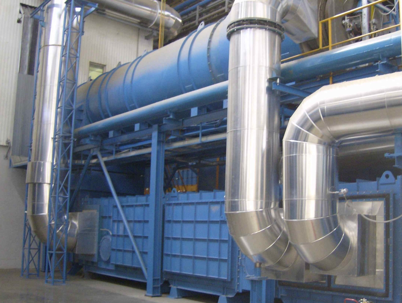
Curing Oven Exhaust Cleaning System
Hot air is transferred to the curing oven to cure the binding agent in the non-cured wool. Emissions from the curing oven are purified in the combustion chamber and they are used for preheating the lamellas before discharge into the atmosphere. The hot air circulation system consists of 2 circulation ventilators, heating chamber and necessary piping. The combustion chamber and heating chamber are equipped with automation for regulation of the flame and temperature. In case of fire in the hot-air or combustion system, the fire extinguishing system is started manually.
Cooling Zone
The hot cured wool leaving the curing oven is cooled by air sucked through the material in the cooling zone. The system consists of a ventilator, buffer, dry filter and piping connecting the cooling zone, ventilator and chimney. In case of fire in the hot-air or combustion system, the fire extinguishing system is started manually.
Cold end of the line
The entire equipment is used for cutting the cured wool into the required length and width and to execute the required packing. The rock wool production line is equipped with a wide saw and several engine-driven, side-adjustable, low-dust saws for cutting the wool block into the required width. The stone wool line is equipped with a transverse saw that works in the tact with the stone wool production line for cutting the wool block into the required length. All cutting modules of the wide and transverse saws work with rotary low-dust saws. The line is equipped with two saws, each on one side of the production line, that clean down the edges of the wool. The saw cleans the edge and the rotary knife processes the cuttings into granules at the same time. The cuttings are crushed in a granulator installed on the conveyor for the wool waste before they are placed on the collecting conveyor. The line is equipped with saws that cut the wool into two or three layers. The number depends on the required thickness of the layers for light material. The stacking device is used for collecting boards from the production line and stacking of a pre-determined number of elements. The board elements are received in up to four rows (in relation to the setting of the saw). Each cycle of the board row speeds up after the cutting (superficial saw) and the boards are transported by a tilted conveyor to the stacking table where the predetermined number of elements is used for the creation of the required stacked parts. The packing and shrinking system is designed for repacking the created packs for rock wool boards and their shrinking in a heated tunnel (for shrinking foil).
Control system – PLC
The control system consists of the control panels of engines (MCC), production line control systems (PCC) and visualisation system.
MCC
All engines are supplied with feeding from motor panels, which control and ensure the operation of the engines directly through the soft starter or through frequency transformers. Each engine has an automatic circuit breaker for engine protection.
PCC
The technological control centre is equipped with several PLCs that are connected via a profibus. All devices are connected to the PCC panels.
Visualisation
- Raw material transport and feeding
- Domed furnace including the dome cooling system and siphon closures
- Drum with the fiberizing machine, swing conveyor and shaping conveyor
- Compression bench, toughening chamber, including heating and combustion
- Cold part of the line
- Finishing combustion equipment of the domed furnace
- Binding system
Gallery
-
- Curing Oven Exhaust Cleaning System

-

- Cupola Flue Gas System
Want to know more? Download product leaflet here or send us an email.